GAPS 2.5.2 Table 1 Inter-Unit
Equipment 1:
Equipment 2:
| Unit | Unit_1 | Inter Unit Spacing (ft) | Inter Unit Spacing (m) |
|---|
GAPS 2.5.2 Table 2 Intra-Unit
Equipment 1:
Equipment 2:
| Unit | Unit_1 | Inter Unit Spacing (ft) | Inter Unit Spacing (m) |
|---|
PTS 12.03.04 Layout of Onshore
Equipment 1:
Equipment 2:
| Unit | Unit_1 | Inter Unit Spacing (ft) |
|---|
| LEGEND: | |
| Input Data | |
| Output |
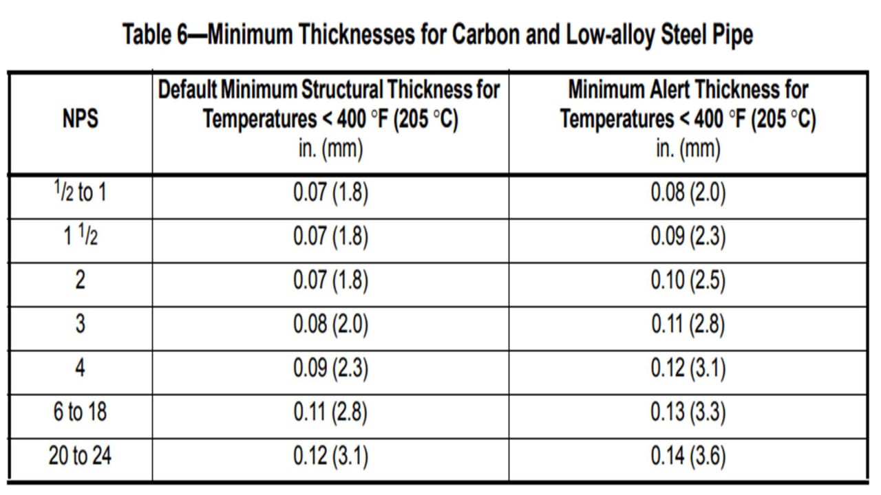
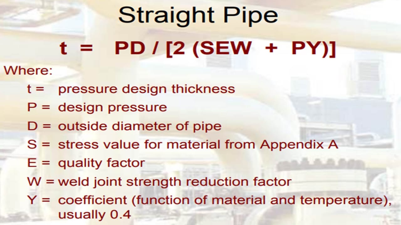
ASME B31.3 Wall Thickness Calculation
|
|
|
|
|---|---|---|
| Pipe Material | ||
| Design Pressure | PSI | |
| Outside Diameter | mm | |
| Stress Value for Material from ASME B31.3 Table A-1 or Table A-1M, S | psi | |
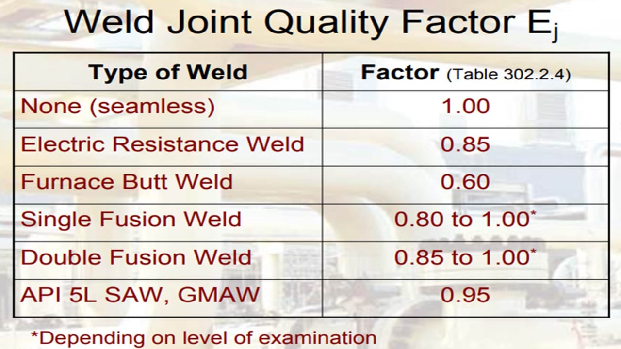
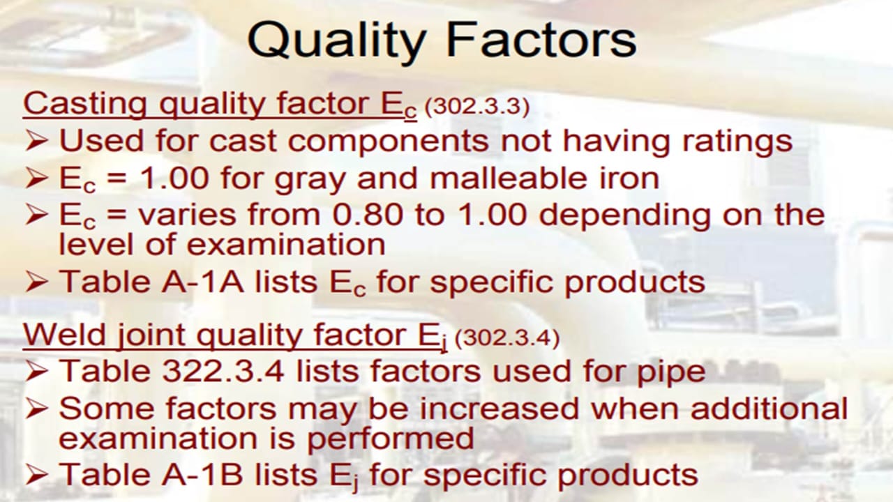
| Quality Factor (E) | ||
| Weld Joint Strength Reduction Factor, W | ||
| Coefficient, Y | ||
| Corrosion Allowance, CA | mm | |
| tmin: | mm | |
| tmin + CA: | mm | |
| trequired: | mm | |
| Minimum Alert Thickness (API 574) | mm |
| LEGEND: | |
| Input Data | |
| Output |
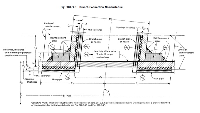
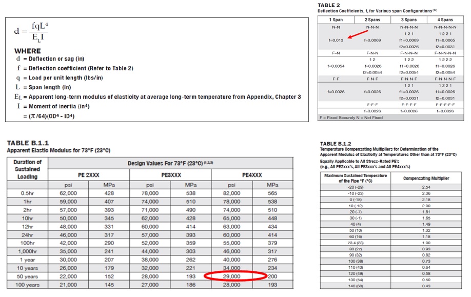
ASME B31.3 Para. 304.3.2 Branch Connection
|
|
|
|
|---|---|---|
| Nominal Pipe Size, Dh | mm | |
| Wall Thickness, WT | mm | |
| Run Pipe Thickness, Th (WT)(Mill Tolerance) | mm | |
| Corrosion Allowance, C | mm | |
| Mill tolerance, MT | % | |
| Material | ||
| Stress Value (from Table 1), S | psi | |
| Coefficient from Table 304.1.1 provided t < D/6, Y | ||
| Quality Factor, E | ||
| Weld Joint Strength Reduction Factor, W |
|
|
|
|
|---|---|---|
| Nominal Pipe Size, Db | mm | |
| Wall Thickness, WT | mm | |
| Run Pipe Thickness, Th (WT)(Mill Tolerance) | mm | |
| Corrosion Allowance, C | mm | |
| Mill tolerance, MT | % | |
| Material | ||
| Stress Value (from Table 1), S | psi | |
| Coefficient from Table 304.1.1 provided t < D/6, Y | ||
| Quality Factor, E | ||
| Weld Joint Strength Reduction Factor, W |
|
|
|
|
|---|---|---|
| Design Pressure, P | psi | |
| Design Temperature, T | °C | |
| Smaller angle between axes of branch and run, β | degree | |
| Nominal Thickness of Reinforcing Pad, Tr | mm |
|
|
|
|
|---|---|---|
| Header Nominal Thickness, th | mm | |
| Branch Nominal Thickness, tb | mm | |
| Effective Length Removed from Pipe at Branch, d1 | mm | |
| Half Width of Reinforcement Zone, d2; d2=d1 or whichever greater | ||
| Final d2 value | mm | |
| Required Reinforcement Area, A1 | mm2 | |
| Area Resulting From Excess Thickness in the Run Pipe Wall, A2 | mm2 | |
| L4 (assuming no reinforcement pad) | ||
| L4 | ||
| Area Resulting From Excess Thickness in the Branch Pipe Wall, A3 | mm2 | |
| tc = 0.7Tb or 6mm, whichever is less | ||
| Final tc value | mm | |
| A4 | mm2 | |
| The total available area (A2+A3+A4) | mm2 | |
| FINAL OUTCOME | ||
| NOTES: A2+A3+A4 < A1 | Reinforcement pad required | |
| NOTES: A2+A3+A4 > A1 | No reinforcement pad is required |
| LEGEND: | |
| Input Data | |
| Output |
Bending Stress - Pipe Support Adequacy Check
|
|
|
|
|---|---|---|
| Outside Diameter (D) | mm | |
| Outside Diameter (D) | m | |
| Wall Thickness | mm | |
| Wall Thickness | m | |
| Weight of Concentrated load | kg | |
| Weight of Pipe per meter | kg/m | |
| Water Weight per meter | kg/m | |
| Allowable Stress (Sa) | Pa | |
| Modulus Elasticity (E) | Pa | |
| Moment of Inertia (I) | mm4 | |
| Pipe Span (L) | m | |
| Hydrotest Weight (pipe+water) | kg/m |
|
|
|
|
|---|---|---|
| Concentrated load at any point | ||
| Maximum Deflection (∆max) | m | |
| (𝑃𝐿3)/48𝐸 | mm | |
| Allowable Deflection | m | |
| L/500 | mm | |
| Bending Stress | Pa | |
| 𝑃𝐿𝐷/8𝐼 | MPa | |
| Uniform distributed load | ||
| Maximum Deflection (∆max) | m | |
| (5𝑊𝐿4)/384𝐸𝐼 | mm | |
| Deflection Ratio | ||
| Maximum Deflection/Allowable Deflection | ||
| Bending Stress | Pa | |
| (𝑊𝐿2 𝐷)/16𝐼 | MPa | |
| Maximum Deflection (5𝑊𝐿4/384𝐸𝐼)+(𝑃𝐿3/48𝐸𝐼) |
mm | |
| Maximum Bending Stress (𝑃𝐿𝐷/8𝐼)+(𝑊𝐿2𝐷/16𝐼) |
MPa | |
| LEGEND: | |
| Input Data | |
| Output |
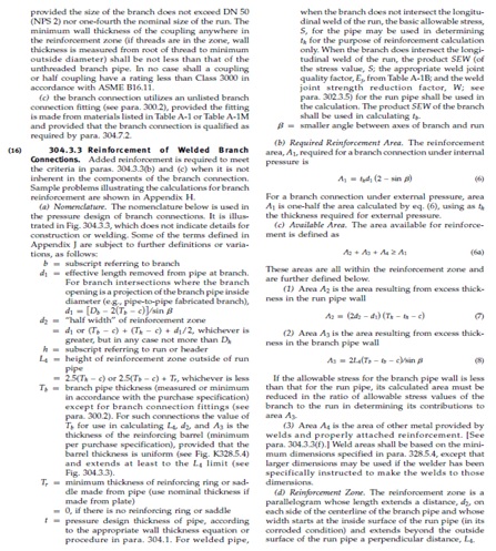
SUSPENSION LENGTH
| Description | DN | |
|---|---|---|
| PN | ||
| Average Wall Thickness (mm) | t (avr) | |
| Weight of Pipe (kg/m) | W | |
| Outside Diameter (mm) | OD | |
| Inside Diameter (mm) | ID | |
| Maximum Allowable Bending Stress (psi) | Ꝋ | |
| Density of Water (kg/m3) | Ბ | |
| Pi | ∏ |
| Description | DN | |
|---|---|---|
| PN | ||
| Average Wall Thickness (mm) | t (avr) | |
| Weight of Pipe (ib/ft) | W | |
| Outside Diameter (in) | OD | |
| Inside Diameter (in) | ID | |
| Maximum Allowable Bending Stress (psi) | Ꝋ | |
| Density of Water (ib/ft |
Ბ | |
| Pi | ∏ |
| Load per unit Length (ib/in) | q | |
|---|---|---|
| Pipe Support Span Length (in) | L | |
| Pipe Support Span Length (m) | L |
| LEGEND: | |
| Input Data | |
| Output |
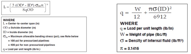
DEFLECTION VALUE
| Outside Diameter (in) | OD | |
|---|---|---|
| Inside Diameter (in) | ID | |
| Pipe Support Span Length (m) | L | |
| Description | DN | |
| NB | ||
| PN | ||
| Deflection Coefficient | f | |
| Load per unit Length (ib/in) | q | |
| Pipe Support Span Length (in) | L | |
| Apparent Long-Term Modulus of Elasticity | EL | |
| Moment of Inertia | I |
| Pipe Deflection (in) | d | |
| Pipe Deflection (mm) | d |